ASE A6 Electrical Electronics Practice Test
6. An engine's starter is cranking slowly. The battery has passed all testing, and the ignition has been disabled for a starter voltage drop test. While cranking the engine, the voltage readings at the battery and starter both indicate 10.03 volts. Technician A says these test results indicate a bad starter. Technician B says there is too much resistance in the positive battery cable. Who is correct?
- A. Technician A
- B. Technician B
- C. Both A and B
- D. Neither A or B
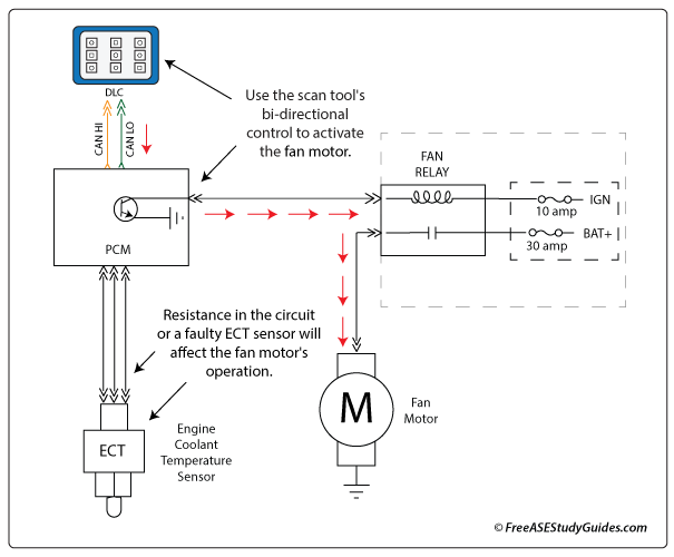
7. The engine's electric radiator cooling fan motor illustrated above does not operate unless commanded ON with a bidirectional scan tool. Technician A says the vehicle most likely has a faulty fan relay. Technician B says a faulty engine coolant temperature sensor or circuit would result in this condition. Who is correct?
- A. Technician A
- B. Technician B
- C. Both A and B
- D. Neither A or B
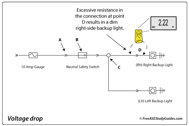
8. The right-side backup light in the diagram above is dim. The other light is normal. Which of the following is causing this condition?
- A. Resistance at point A.
- B. An open at point B.
- C. An open at point C.
- D. Resistance at point D.
9. The resistance between pins 6 and 14 of the OBD II connector above measures 60 ohms. Technician A says this is correct. Technician B says the modules must be powered down or the battery disconnected to test resistance in the CAN bus. Who is correct?
- A. Technician A
- B. Technician B
- C. Both A and B
- D. Neither A or B
10. A vehicle's air conditioner blower motor only works at high speed. Technician A says to check the blower motor resistor. Technician B says this is most likely caused by a loose ground connection. Who is correct?
- A. Technician A
- B. Technician B
- C. Both A and B
- D. Neither A or B