Resistance in the CAN bus
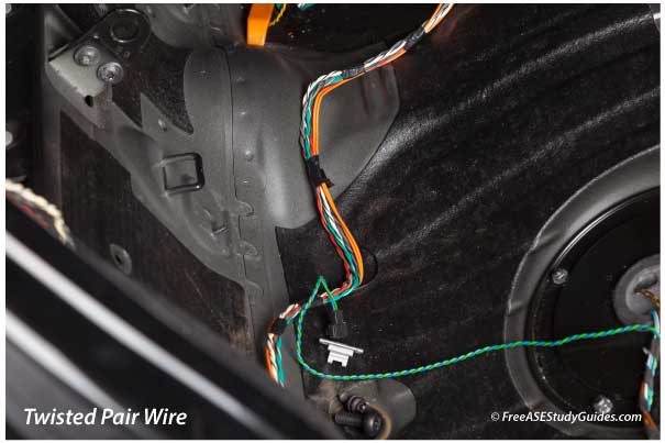
Resistance is the opposition or hindrance to the flow of electrons in a circuit. Connectors, switches, and wires all offer some resistance. For example, twisted pair wire typically contains 120 ohms of impedance, and the CAN bus has a 120-ohm resistor at each end. These resistors are often located inside two control modules to normalize voltage and prevent reflections from corrupting the data on the bus.
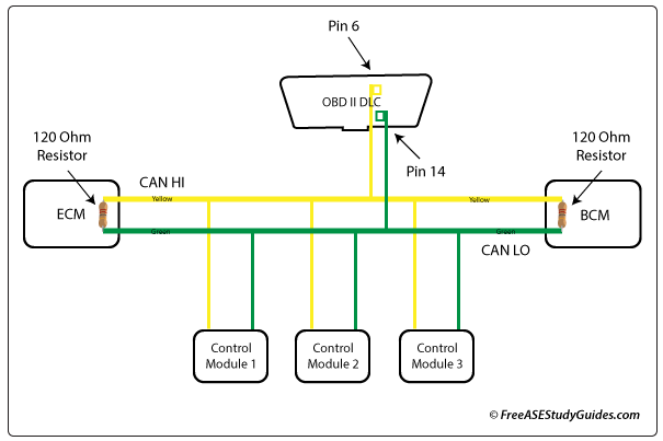
Two 120-ohm resistors provide 60 ohms of resistance because two 120-ohm resistors installed parallel have an equivalent resistance of half the resistor (120/2) or 60 ohms. One faulty resistor and one good resistor result in 120 Ohms of resistance.
Resistance Tests
There are two different resistance tests shown below. Test A measures the resistance between the CAN HI and CAN LO pins on the ECU containing one of the resistors (120 ohms). Test B measures the resistance of the CAN bus containing two controllers, each ECU with a 120-ohm resistor.
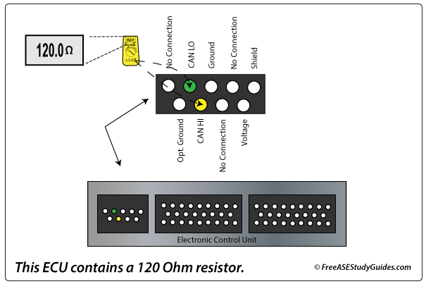
(A) The resistance between the CAN HI and CAN LO pins on the ECU (usually the ECM, PCM, BCM) containing the resistor will measure 120 ohms.
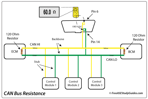
(B) The resistance of the CAN bus, with two modules connected containing the 120-ohm resistors, will measure 60 Ohms because two 120-ohm resistors in parallel (equivalent resistance) produce 60 ohms of resistance.
Gateways
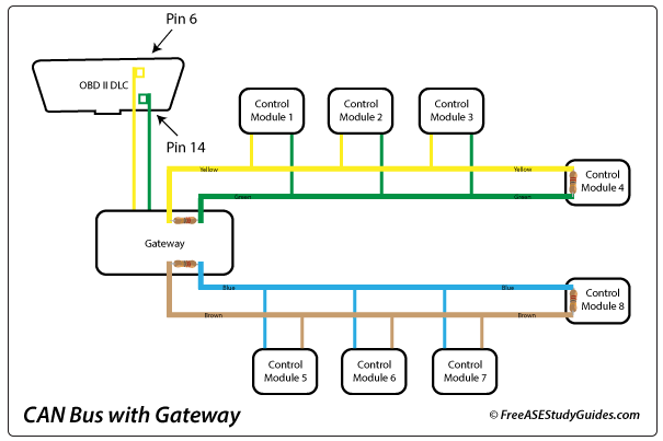
Some vehicles have a gateway. In the example above, the DLC and both networks connect to a gateway. Check the manual to locate these connections. Measurements on a CAN bus with a gateway must be measured in another place, like an easy-to-access control module or the CAN HI and CAN LO connection to the network on the gateway.
The resistance between the CAN HI and CAN LO pins and ground on the DLC should be infinity or megaohms. When there is no action on either CAN line, the voltage is around 2.5 Vdc. If CAN HI shorts to CAN LO, the voltage will remain around 2.5 Vdc on both lines.
CAN Waveforms
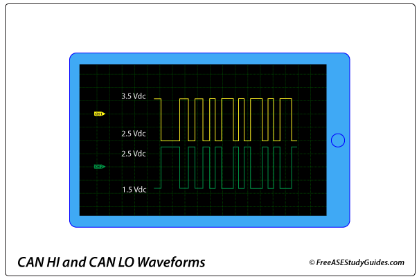
When a module sends a message, the CAN HI line (Yellow) increases above 2.5 Vdc, and CAN LO (Green) decreases below 2.5 Vdc. When compared, high and low CAN bus waveforms mirror each other.