Hydraulic Flow Charts
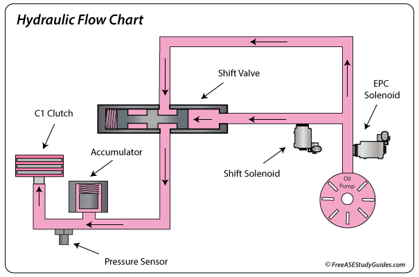
Hydraulic flow charts display fluid flow through the transmission's solenoids, valves, and oil circuits. Hydraulic flow charts, shift solenoid charts, and clutch and band application charts help diagnose an automatic transmission. The oil circuit chart above shows fluid flow through an EPC solenoid, shift solenoid, and shift valve.
Many transmissions use an EPC solenoid to adjust pressure for wear and operating conditions. Today's transmissions perform better by dedicating a PC (pressure control) solenoid for each clutch circuit. Timing is vital as one clutch engages the other releases. The TCM can adapt to wear and operating conditions, increasing pressure for a leaking clutch seal or an increased load and gradually increasing the duty cycle for a smooth clutch application.
Shift Solenoids
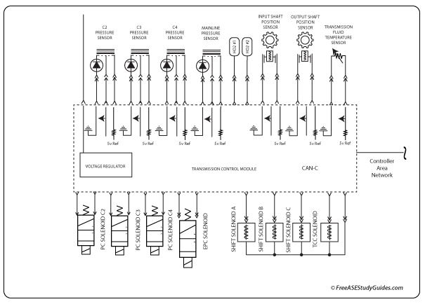
Transmission control modules use information from internal sensors and sensor signals received over the network (CAN). The TCM activates shift and pressure control solenoids based on inputs from both engine and transmission sensors.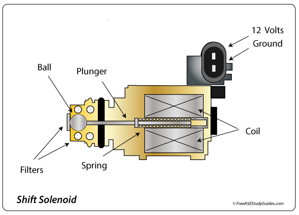
Electronically controlled transmissions use shift solenoids to control flow. Standard on/off solenoids have only two positions, either on or off. They consist of a coil of fine wire wrapped around a spring-loaded plunger that, when energized, moves the plunger, either opening or closing a hydraulic circuit. When deactivated, the plunger is pushed by a spring to its at-rest position. Most modern transmissions control the solenoid from the ground side by pulsing the circuit on and off (Pulse Width Modulation).
Clutch to Clutch Shifting
Many transmissions use an EPC solenoid to adjust pressure for wear and operating conditions. The TCM can adapt to wear and operating conditions, increasing pressure for an increased load or a leaking clutch seal. It provides a softer shift by gradually increasing the duty cycle for a smooth clutch application.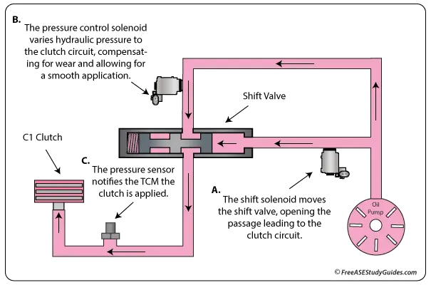
When the TCM activates the shift solenoid, the shift valve moves to the left. This action opens the passage from the pressure control solenoid to the clutch. The pressure sensor notifies the TCM when pressure increases, and the clutch engages.