Brake Switch Testing
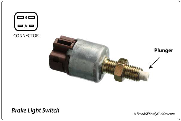
Modern brake switches have four or more pin connectors. A standard brake switch has a four-pin connector that controls two circuits. The brake switch voltage signal affects more than the stop lights. For instance, the ECM requires this signal for the shift interlock switch on automatic transmissions; a faulty brake switch will prevent an automatic transmission from shifting out of Park.
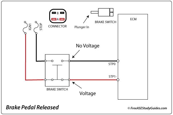
The brake switch in the illustration has continuity between two pins and an open circuit on the other pair. When the brake pedal is released and at rest, the brake switch's plunger is pushed in by the pedal return spring pressure. When the pedal is depressed, the plunger extends, operating the brake switch.
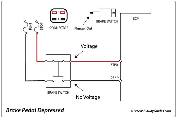
When the pedal is depressed, the voltage signals switch. The controller knows the brake pedal has been depressed when the voltage signals change. Therefore, if either voltage signal is out of correlation (incorrect), the ECM will set the trouble code (P0504 BRAKE SWITCH A/B CORRELATION).
A faulty brake switch can affect the brake lights, shift interlock, torque converter clutch, ABS, traction control, and cruise control systems. Use a scan tool to check codes and a multimeter for voltage and continuity in the brake switch and its circuit.
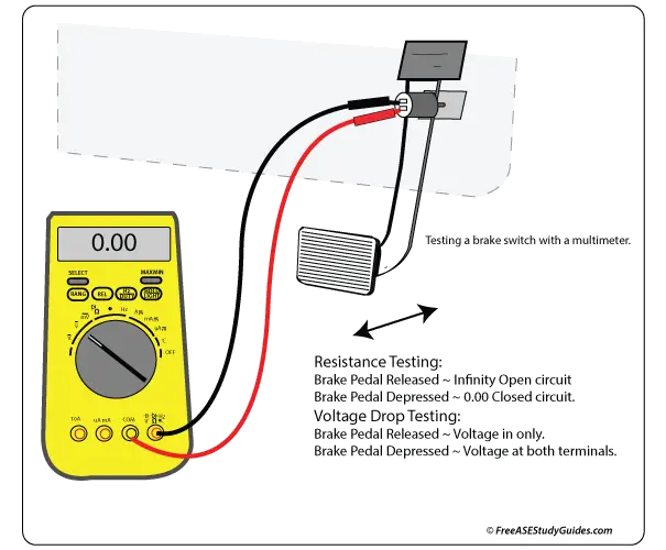
Some switches have larger pins for the brake lights and smaller ones for the controller. The manufacturer's manual will provide a diagram to identify the pins that affect the vehicle's brake lights. Always confirm where a wire leads before testing. Computer modules are sensitive, and one wrong move could spell disaster.