Door Lock Circuits
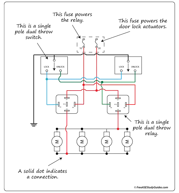
The door lock circuit in the diagram above uses ground-side switching (negative pulse control) containing two SPDT single pole dual throw relays. The system uses voltage reversal to control the direction of the door lock actuators. Apply voltage to one wire of the motor and ground to the other, and the motor moves in one direction. Reverse the polarity, and the motor moves in the opposite direction. There are two relays: a lock relay to lock the door and an unlock relay to unlock it.
Positive Pulse Door Locks
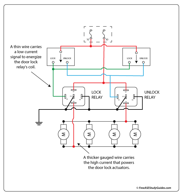
A positive pulse door lock circuit is very similar. Instead of the ground circuit, the power circuit energizes the relay's coil. Some older door lock systems found on domestic cars omit the relays and use thicker gauge wiring instead. Late-model vehicles use control modules offering more door lock and security system control features.