A/C Compressor Clutch Coil Test
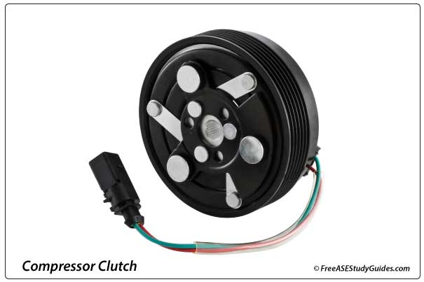
An A/C compressor clutch coil is a simple device made of fine wire windings wrapped into a coil. When current is passed through the coil, it creates a strong magnetic field that pulls a splined hub into contact with the spinning pulley. This action engages the compressor.
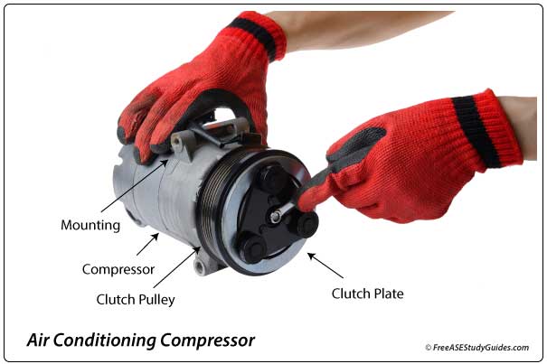
The compressor clutch coil engages and disengages the compressor from the engine. When the ECM energizes the coil relay, it locks the clutch plate to the spinning pulley, causing the compressor shaft to spin.
Clutch Coil Testing
Take great care when running these tests because the coil's harness plug is small and may be difficult to test. Always use caution when working around hot or spinning parts. Check the circuit for proper voltage before testing the coil for resistance. Before testing, visually inspect the coil for overheating and cracking. Heat expands the coil and creates breaks in its windings.
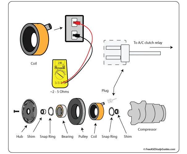
Voltage Test: Remove the plug from the clutch coil and activate the A/C system by placing the selector on cold. Using the 20-volt setting on the DVOM, check for battery voltage at the harness connector. Test the coil for resistance if there is battery voltage at the plug.
Resistance Test: Perform an A/C clutch coil resistance test with an Ohmmeter. Typically, a clutch coil should be between 2 and 5 Ohms, and any reading below 2 Ohms or over 5 Ohms indicates a bad coil. A reading of 0.00 indicates that there is a shortage in the windings. A reading of O.L. or infinity indicates an opening in the windings.
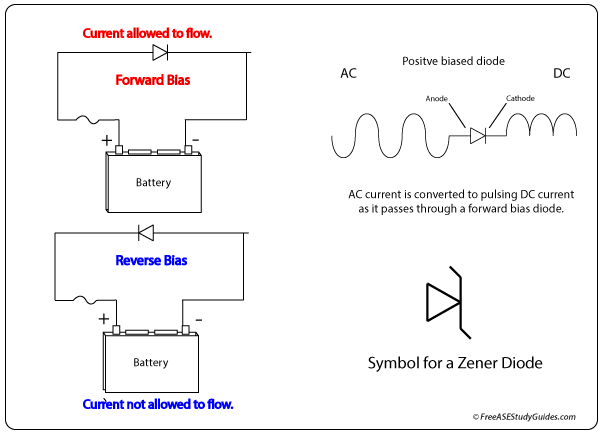
The coil contains a clamping diode to prevent voltage spikes when the clutch suddenly disengages. It protects relay contacts and the control devices, such as the PCM, the BCM, or the ATC module.
The diode should be tested as well. Diodes are like one-way check valves; the current flows in one direction but not the other. Many multimeters have a selection or function for testing diodes. Many coils contain zener diodes that allow current, but only up to a certain threshold. For more clarification, check the manufacturer's manual for specifications and special procedures for performing the test.