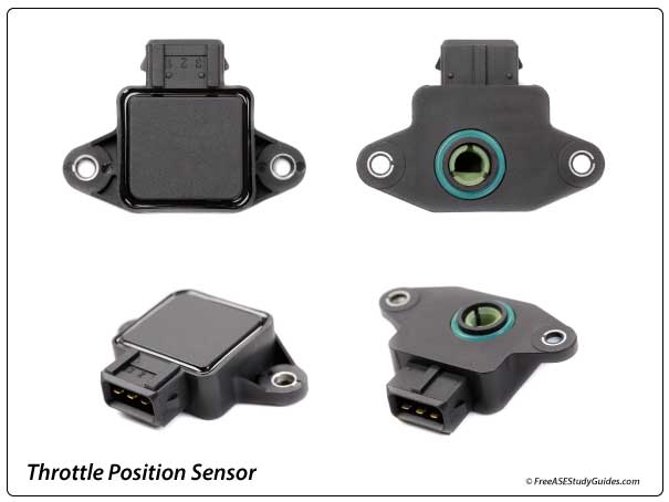
Throttle Position Sensor
Throttle position sensors indicate the engine's throttle angle to the engine control module. Most have extra pins for functionality, such as cruise control traction and electronic stability control.
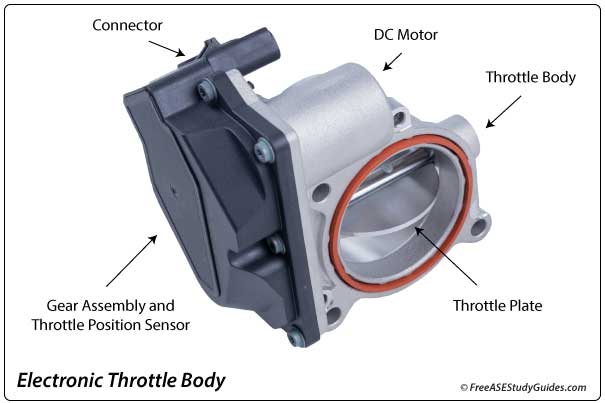
Electronic throttle actuators and throttle bodies contain position sensors. Electronic throttle actuators and throttle bodies contain position sensors. The ECM uses input from two throttle position sensors in the throttle actuator and the accelerator pedal position sensor to calculate and check the throttle angle on a modern engine.
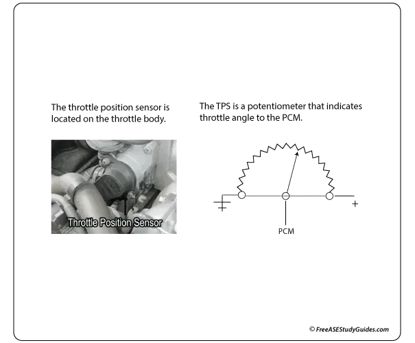
One of the leads is connected directly to the computer's 5-volt voltage supply, and the other lead connects to the ground circuit. Finally, the third wire, the signal circuit, is connected to the movable arm that swipes across an internal resistance strip. The signal circuit sends a varying voltage signal back to the ECM, indicating the throttle plate's angle and the driver's intentions.
It's attached to the throttle plate shaft and changes output voltage as it opens and closes. The output voltage will be low or around 0.45 volts when the throttle is closed and will be high or 4.5 volts at (WOT) Wide Open Throttle. The ECM adjusts the fuel injection and ignition timing as the throttle plate moves. For example, if the driver suddenly accelerates, the ECM will register this 4.5-volt signal and increase the fuel injector pulse width to compensate.
The ECM and the TCM share this sensor's output over the network. The (TCM) Transmission Control Module uses the TP sensor's signal to indicate load and the driver's intentions and determine the shifting schedule. For example, if the throttle plate approached WOT (4.5 volts) suddenly, it would indicate it was time for a downshift.