ASE A2 Automatic Transmission Practice Test

26. An automatic transmission is hard shifting only in second gear. All other gears are operating correctly. Technician A says this could be caused by a faulty accumulator. Technician B says the accumulator may have a broken spring. Who is correct?

  • A. Technician A
  • B. Technician B
  • C. Both A and B
  • D. Neither A or B

26.

Answer A is wrong. Accumulators are designed to improve shift feel.

Answer B is wrong. Accumulators contain springs that provide tension for the accumulator's piston. There are several accumulators in an automatic transmission.

Answer C is correct. Both Technicians are correct.

Answer D is wrong. Both Technicians are correct.

27. Technician A says that a shift solenoid is a hydraulically controlled device used for shift control. Technician B says shift solenoids are computer-controlled actuators that can be diagnosed with a scan tool. Who is correct?

  • A. Technician A
  • B. Technician B
  • C. Both A and B
  • D. Neither A or B

27.

Answer A is wrong. A shift solenoid is an electronically controlled actuator used by electronically controlled transmissions to control fluid flow.

Answer B is correct. They can be diagnosed with a bidirectional scan tool and a digital multimeter.

Answer C is wrong. Technician B is correct. Learn more about shift solenoids in the Read more... section.

Answer D is wrong. Technician B is correct.

Automotive Relay

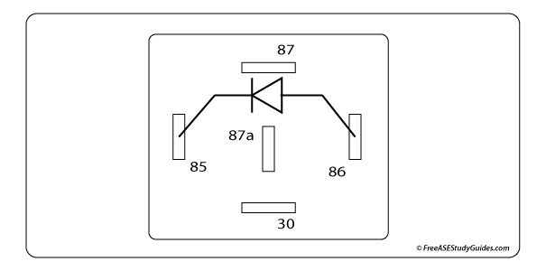
28. The electrical item in the illustration above represents:

  • A. A single pole solid state relay.
  • B. A single pole dual throw electromechanical relay.
  • C. A pulse width modulated solenoid.
  • D. A single throw solid state relay.
Automotive Relay

28.

Answer A is wrong. Relays may be electromechanical or solid state.

Answer B is correct. It's a standard SPDT (single pole dual throw) electromechanical relay.

Answer C is wrong. Control modules use relays to control high-current devices.

Answer D is wrong. Answer B is correct.

Diagram of automotive PCM engine control system.

29. Component A in the schematic diagram above is:

  • A. A connection in the signal circuit for TP sensor.
  • B. A splice in the signal circuit for TP sensor.
  • C. A splice in the ground circuit for TP sensor.
  • D. A connection in the reference circuit for TP sensor.

29.

Answer A is correct. This is the schematic symbol for a connector.

Answer B is wrong. A splice is denoted as a solid black dot that connects two wires.

Answer C is wrong. This is the connector for the signal circuit of a TP sensor.

Answer D is wrong. The reference voltage circuit is labeled 5V ref.

30. Technician A says a faulty throttle position sensor affects engine and automatic transmission performance. Technician B says that the throttle position sensor indicates vehicle speed to the transmission control unit. Who is correct?

  • A. Technician A
  • B. Technician B
  • C. Both A and B
  • D. Neither A or B

30.

Answer A is correct. Sensor input like the (TPS) Throttle Position Sensor is shared with different control modules over the network. The TPS signal is essential to both engine and transmission performance.

Answer B is wrong. The TPS indicates the engine's throttle angle and load, and the (VSS) vehicle speed sensor indicates vehicle speed to the TCM on vehicles with electronic automatic transmissions.

Answer C is wrong. Technician A is correct.

Answer D is wrong. Learn more about TP sensors by clicking the Read more... button.