Heated Oxygen Sensors
The ECM operates in two run modes, open loop and closed loop. In open loop, the ECM relies on a set of rules in PROM to make fuel delivery decisions. It is constantly monitoring the oxygen sensor to enter closed loop. In closed loop, the ECM relies on input from the O2 sensors and other sensors to calculate the air-fuel ratio.

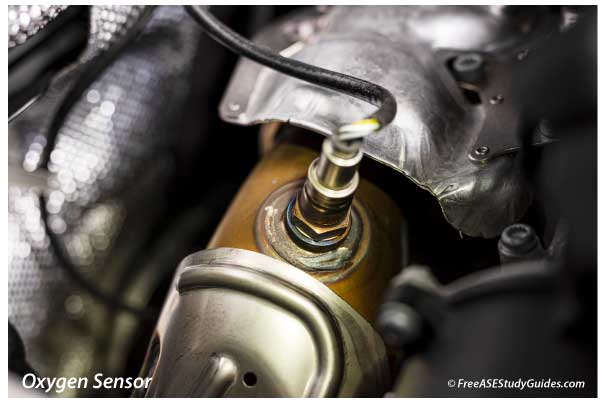
Oxygen sensors are located in the exhaust manifold or exhaust pipe of the engine's exhaust system. The sensor measures the oxygen content in the exhaust stream. It sends an analog voltage signal to the ECM between 0 and 1 volt. The ECM uses this signal to control and adjust the engine's air-fuel ratio while in closed loop.
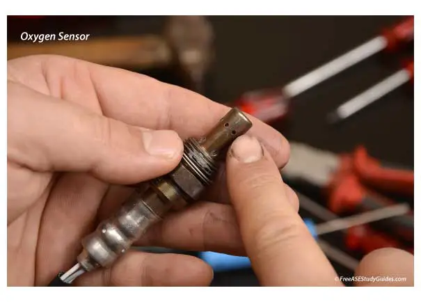
An oxygen sensor produces a reliable voltage signal after it reaches 600° F. This is due to the design and materials used to create the sensor. The zirconia sensing element is the most common type: a voltage conductor when it's hot and a resistor when it's cold. Oxygen passing through the element affects the voltage signal. It produces a high voltage signal (.90) when the air-fuel mixture is rich and a low signal (.10) when it is lean.
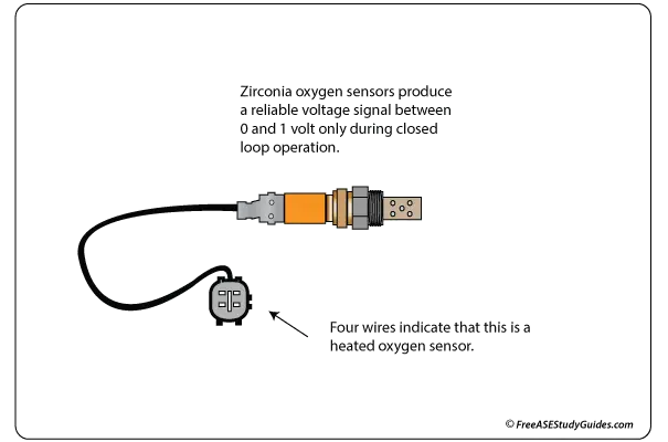
The sensor can have one to four wires. A one-wire or two-wire sensor does not contain a heater circuit or send a voltage signal until it reaches operating temperature. Three-wire and four-wire O2 sensors have a heater that brings the sensor to its operating temperature to produce a voltage signal sooner than sensors without a heater. Therefore, a heated oxygen sensor is more efficient than an unheated sensor. The only difference is that the three-wire sensor shares a common ground between the heater and sending circuits.